
Description.
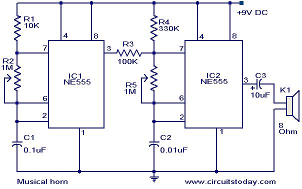
Here is a simple circuit diagram of a simple musical horn using two NE555 ICs. Two ICs are wired as astable mutivibrators. The output of first multivibrator is given to the discharge (pin 7) of the second astable multivibrator. The combined effect of the astable multivibrators produces a musical tone at the output.
Circuit diagram with Parts list.
Notes.
- The sound effect can be adjusted by varying the POTs R2&R5.
- The speaker can be a 8 Ohm tweeter.
- The circuit can be powered from a 9V PP3 battery.
- The ICs must be mounted on holders.
- All capacitors must be rated 15V.


0 comments:
Post a Comment