Description.
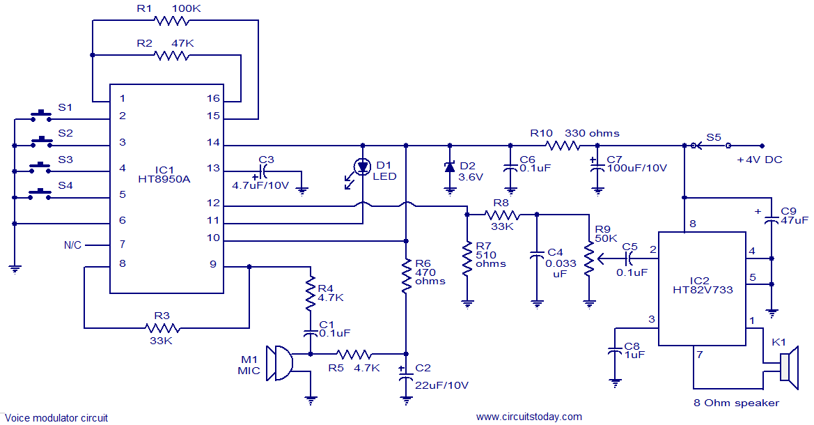
This is a very versatile voice modulator circuit using IC HT8950A from Holtek Semiconductors. The IC is capable of creating 7 upward or downward steps on the frequency of the input voice at a rate of 8Hz. There is also two special variation effects namely Vibrato mode and Robot mode. This circuit finds a lot of application in systems like telephone, speech processors, toys, mixers etc. A microphone is used to pick up the input voice. Push button switches S2 and S3 can be used for the upward and downward frequency stepping .Push button switch S1 can be used to activate Vibrato mode and push button switch S4 can be used to activate the Robot mode. IC HT82V733 (also from Holtek) is used to amplify the output of the voice modulator.LED D1 indicates the voice level.
This is a very versatile voice modulator circuit using IC HT8950A from Holtek Semiconductors. The IC is capable of creating 7 upward or downward steps on the frequency of the input voice at a rate of 8Hz. There is also two special variation effects namely Vibrato mode and Robot mode. This circuit finds a lot of application in systems like telephone, speech processors, toys, mixers etc. A microphone is used to pick up the input voice. Push button switches S2 and S3 can be used for the upward and downward frequency stepping .Push button switch S1 can be used to activate Vibrato mode and push button switch S4 can be used to activate the Robot mode. IC HT82V733 (also from Holtek) is used to amplify the output of the voice modulator.LED D1 indicates the voice level.
Circuit diagram.
Notes.
- The circuit can be assembled on a Vero board.
- Do not give more than 4.5v to the circuit.
- Switches S1 to S4 can be miniature push button switches.
- S5 can be a miniature ON/OFF switch.
- K1 can be an 8 ohm speaker.
- IC1 and IC2 must be mounted on holders


0 comments:
Post a Comment